6
You are using an out of date browser. It may not display this or other websites correctly.
You should upgrade or use an alternative browser.
You should upgrade or use an alternative browser.
Complete J519 CECM pin-out
- Thread starter phd-12v
- Start date
ChancreScolex
Ready to race!
Is this accurate for a 2012 Autobahn manual GTI w/ kessy? Trying to figure out if pin 30 on the brown connector (brown wire) is my clutch position sender. Need it for a remote start bypass. Finding misinformation/conflicting information everywhere else.
toniphoto07
New member
Hi guys!
I would like to know what do I need to do.
So, I bought a mk6 light sensor and auto switch and I want to upgrade that in a very old car without vw harness.
Now I have an analog light switch so I have some problems with wiring this all correctly.
Thank you for your time!
I would like to know what do I need to do.
So, I bought a mk6 light sensor and auto switch and I want to upgrade that in a very old car without vw harness.
Now I have an analog light switch so I have some problems with wiring this all correctly.
Thank you for your time!
Hi, and please forgive if this is not right on topic, but I'm trying to get some info on the schematic/function for the 'E229' (I think?) emergency flasher switch on the Mk6 Golf. I have a 2013 TDi and I've put a GPS mount and mini power supply 5VDC o/p socket exactly where the Emergency Flasher switch was, just because the location was spot-on, thinking I could simply add a tiny Momentary Pushbutton and an LED to sub in for the switch, just below it. Problem is, looking at the 4 pins on the switch, I can find zero difference in continuity between any 2 pins when the OEM PB is depressed. I'd guessed that there was a contact closure on a line to the ECU or via CAN bus controller or such, but I can find zero info anywhere! Anyone have an idea what's going on in that switch? I will simply pull it apart if I get desperate, but the info would surely help before that.
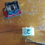
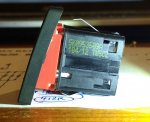
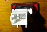
OK, above Q is moot, as I took the Emergency flasher switch (PN- 5K0953509A) apart.
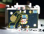
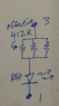
Turns out there was a problem between DVM probes and chair, and it is in fact a simple (25 ohm resistive pad) contact closure, and a (3X parallel 1.24K) resistor chain to an LED, each using 2 of the 4 pins. Equivalent cct and physical arrangement shown in pics. Note that 3 R's are used in parallel for power handling.. dropping ~(14 - 2)V across 412R is ~1/3Watt..
I don't know what is being activated by the 'switch' across pins 4 and 5; it could be the primary side of a relay cct or a pin pulled down on the ECU, but anyone playing with this would be wise to assume that each of pins 4 and 5 must be isolated from the 12V rail and GND. It's blizzardy outside so I am not going to measure levels right now.. but note that this switch is active at all times. Just a drop of some info that I could not find anywhere.
Attachments
-
 sw apart.jpg179.6 KB · Views: 214
 -
 switch.jpg141 KB · Views: 229
 -
 cct phys.jpg83.9 KB · Views: 266
 -
 LED SCH.jpg40.8 KB · Views: 198
 -
 pin ID.jpg64 KB · Views: 188