DIY: 8 Sensor OPS Retrofit and PLA 2.0
Here goes my first write up. First of all thanks to thebush121 for buying the sensors and letting me take pictures/help with his car and phd-12v for wiring tips. Also thanks to the authors of the tutorials we used to remove bumpers, route wires, etc. Scroll to the end for the PLA 2.0 specifics! When purchasing the PLA 2.0 kit make sure to request 4 of the angled sensors!
Anyway on to the 8 sensor OPS retrofit!
Some background info:
2011 Golf TDI 2 door
RCD-510 (does not have plug for RVC) OPS works great as you will see
Bold Sport OPS 8 sensor kit
PLA 2.0 Background info:
2012 Golf TDI 4 door
RNS-315
For the TL;DR crowd... Finished product.
Parallel Parking
http://youtu.be/PsABB-AE_9Q
Bay Space Parking
http://youtu.be/1A5aTp2LyRQ
Tools required:
Rear Bumper Removal
We will start with the Rear Bumper removal and sensor install.
First remove the outer lights by pulling back the carpet, unclipping the wires, and unscrewing the white screw. Pull the lights straight away from the car.
Removing the Rear bumper is actually pretty simple. Here are the screw locations:

Then remove all 12 screws (4 in each wheel well and 4 on the bottom edge). You DO NOT need to remove the valance; it all comes off as one piece.

There will be clips on either side on the quarter panel. Unsnap these by pulling straight out from the side of the car

Next pull the bumper cover up and over these three clips.

Use trim tools to push up on these two clips while pulling the bumper cover away from the car
Do these steps on both sides, preferably at the same time with two people and the bumper will come off. Don’t forget to remove the electrical connector for the license plate lights before walking away with the bumper cover! When placing the cover back on it’s the reverse of removal but remember to line up the lip below the hatch with the groove in the bumper cover or your hatch won’t close all the way! (Ask me how I know….)

Now you have a naked car! See that harness laying to the right? That’s the old license plate harness. Bring it inside with the bumper cover you will need it.
Sensor install:

You will see 4 of these outlines inside the bumper cover, use a small drill bit to punch through the center of them from the inside of the bumper. Clean up these spots if your cover is dirty like this one.

Then tape the bumper up with painters tape/masking tape on the outside to protect the paint.

Then drill the holes with the tapered bit to about 11/16 or 18mm. Test fit the sensors and if they are a little tight or don’t fit flush on the outside without force drill it out just a little more. Just take it slow on the first few, can always make a hole larger but can’t make it any smaller!

These are the sensors after gluing. We used a silicon adhesive but once we got to the front bumper one kept falling off hence the recommendation of gorilla glue epoxy. Basically just remove tape, sand the hole to remove any burrs, and sand inside under the sensor holder to give the glue something to stick to. Then mix the epoxy and put a dab on the sensor holder and stick it on the bumper in a way that makes it flush on the outside of the bumper. You might have to hold it there for a bit till glue gets tacky enough to hold the sensor in place. Here are some pictures of the finished bumper with wiring installed. The wiring will basically clip in where the license plate harness was. You will get a few more clips in the kit to attach the wiring to the factory points.


LET THE GLUE DRY FOR AT LEAST A FEW HOURS BEFORE MESSING WITH THE SENSORS!
You will need to splice in the old license plate power as this new harness replaces the license plate harness. Just cut the old harness to the length you need and remove the pins from the end of the new harness pictured above by removing the purple C piece you can see above, unsnapping the body, and use the pin removal tool. Both old and new will have the same color code for the lights brown and grey/brown. (pins 1+2 on the new harness) Fill the holes with silicon on the harness before snapping it all back together to retain water resistance. Take the two pins liberated from the new harness, cut off the pins, strip the wires and solder/heatshrink to old harness. If you ever have to remove the bumper again you should be able to disconnect both sets of wires at the entry point to the body. (Sorry no pictures of this one… plain forgot. I’ll get some when I install the PLA 2.0 on my Golf)
Front Bumper:
The front bumper is a repeat of the drilling/sanding/gluing/wire routing process so I won’t go over that one again. To pull the front bumper use this DIY (we didn’t take pictures as it was day two and we wanted to get it done) http://www.vwgolf.net.au/showthread.php?7265-MK6-Front-Bumper-Removal
Only caveat I have with that DIY is after taking the bumper off I believe the upper grill does not need to be removed first. Just take off the screws on top and remove it with the rest of the cover as it just snaps into it.

Now that you have your sensors glued and attached pull the foam off the front bumper. Now test fit it into the cover. You will have to cut notches into the foam for the front two sensors as shown above and in the next few pictures.


In the above picture you will see the wire on top of the foam. Glue your plastic wire holders to the bumper cover above the foam and snap this wire into them once the glue dries.
So at this point you should have two bumpers with sensors + harnesses installed and a front foam piece with notches cut into it. Oh and a naked car that will become nakeder. Is that even a word? Haha.
Wiring:
Now the difficult part of this this DIY and the source of most of the confusion around it….
A big warning here, do not try to run/test PDC without everything connected (all 8 sensors and both buzzers). IT WILL NOT WORK. IT WILL BEEP AT YOU ONCE THEN GIVE YOU THE FINGER NO MATTER HOW YOU CODE IT. It’s a safety measure to keep people from using a not fully functional system and hitting something. So if you want to test it before putting the car back together connect everything!
First things first, lets get the module wired up to canbus, power, and the button.
The PDC module’s large brown connector is the only one we are dealing with at this moment. This is a good time to disconnect your battery if you haven’t already. Also use the cloth tape to tape up any naked wires on any of the PDC harnesses to prevent rattles before going any further.

This is where we chose to mount the module. Pop the trim off by putting a screwdriver or key in the notch and prying.

Remove the door sill trim by simply pulling up on it by the kick panel and working your way down. Be careful it's easy to break clips. Once this is up the kick panel will pull right off, no screws or clips. Then remove the fuzzy panel under the dash by twisting the two thumb screws.

Remove the radio by using a trim tool to pry the surrounding trim off carefully and removing the four screws surrounding it. Do the same with the climate control below it. If you unplug the airbag light you will have to clear a code in the airbag module with VCDS FYI. Also remove the gearshift trim with your trim tools (move the gearshift to the rear most position to give yourself room) and unscrew the two screws holding the buttons /storage tray. Disconnect any wiring and pull the tray out. Pop out whatever blank you want and pop your snazzy new PDC button in.
In the picture above you can see the orange CANBUS wires already fished through the dash from the passenger side those go all the way to the CAN Gateway above the accelerator. Fish all other wires except the purple buzzer and brown ground to the radio opening including the wiring for the button.
Remove the foot vents on the drivers side. Depending on the year of your car there will be either two screws or one screw and a zip tie. It will probably hit you in the face when unscrewed.
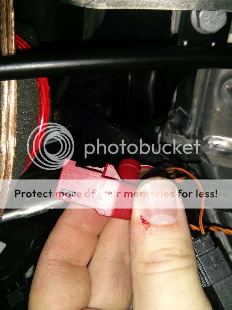
Once the footwell vent is off you will see this guy. Disconnect it (without cutting your thumb like me) and to remove the housing, cut the ziptie, press the red tab seen in this picture, and slide the red housing off. Depending on the model of your car the pins may vary but the two needing to be removed will be the same orange/black and orange/brown of the PDC wires. On this Golf they were pin 6 and 16. Remove these from the housing by pressing the spring in the window and pulling. If you’re confused do a search on Youtube for VW terminal removal.

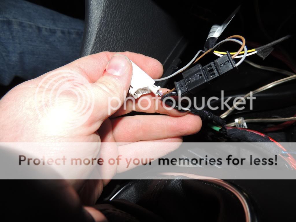
These wires will plug into the female plug from the PDC (pin1/3) and the male will plug into the gateway in the same spots as the wires you removed. You should end up with the above once you slide the red housing back on to the gateway connector. Which you can now reconnect, CANBUS COMPLETE! Don’t grab a celebratory beer quite yet though.
(On a side note if anyone was wondering where the footwell temperature sensor for climatic is installed by VW its in the background)
Now on to the button and power!

Using your terminal tools again remove the brown and grey wires from the ESP button and plug them into the familiar female connector above into pins 1/3. Make sure to go brown to brown and grey to grey. Then plug the male brown and grey from the PDC button into the ESP button. You should end up with the above.
Now whip out those solder skills and solder the remaining green/black wire to +12v on the power outlet. Cover with electrical tape or heat shrink. The connector on the green/black PDC wire can be cut off. I believe it was meant to go into the fuse panel but it doesn’t fit into any of the holes that we tried. Plus this is so much easier.
You can now connect the buttons/+12v outlet and put it back in place.
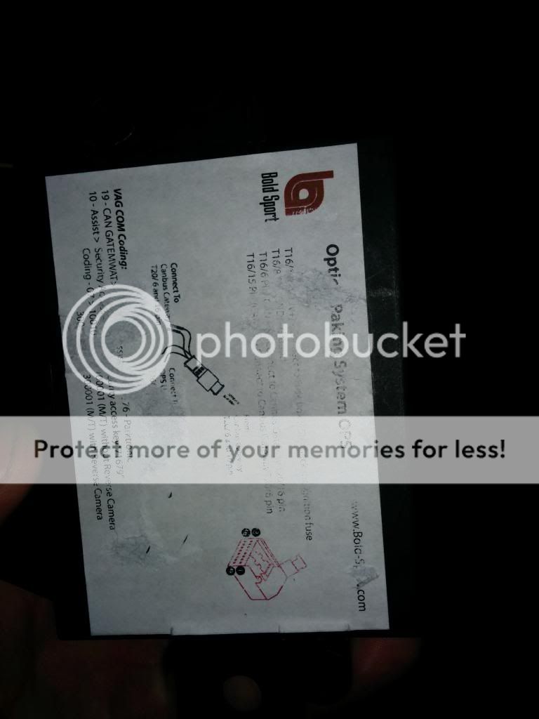
Pull the shell off the module connector and plug the button wire or wires into the correct place. I don’t know the correct pins off hand but the label on the module will say. As you can see this one got messed up by double sided tape.
You will see a grounding nut behind the kick panel you removed attach the brown ground wire there.

Now the Rear bumper… This is on the passenger side right next to the bumper mount and is the grommet the license plate light passes through. Cut a small hole and push the rear interior harness through after taking the shell off the connector to make it smaller. Ziptie it to the license plate wire once you have the length you want outside the car.

Another picture of it.

It will come up on the other side of this carpet. Remove the bottom hatch trim by pulling the sides in then the bottom over the luggage hooks and straight up. Be careful the clips break easy. Run the wire under the back seat and down the passenger side to the module location. Coil up any remaining wire behind the carpet above.
Run the purple buzzer wires back to this same spot and mount the buzzer with double sided sticky tape behind the carpet.
Rear bumper wiring is now complete, huzzah!
The front bumper is a bit trickier.
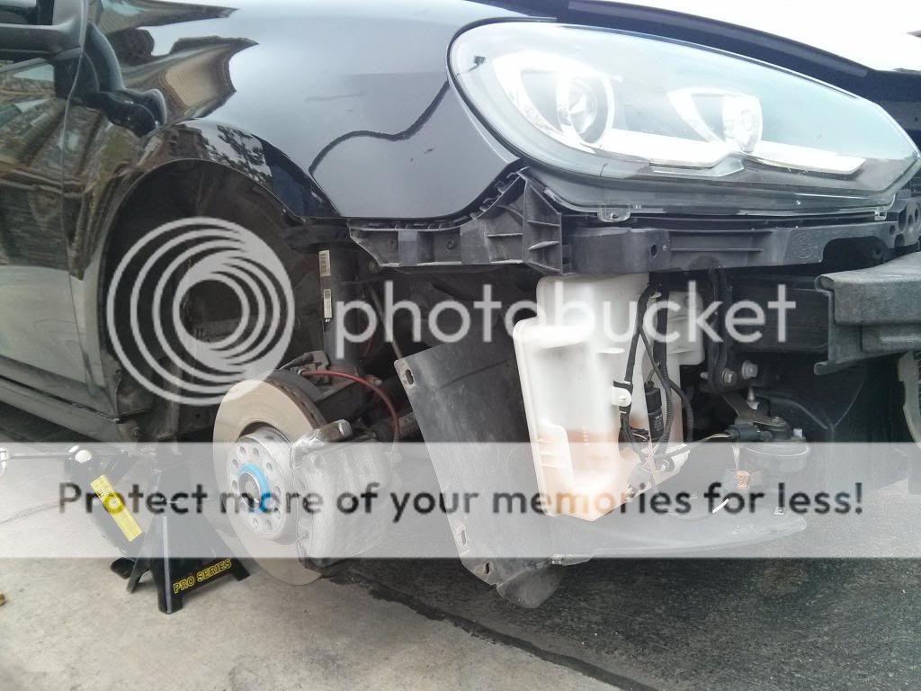
Pull the wheel and the wheel well cover reveal your wires path. There is a channel in the fender for easy wire routing from the washer fluid reservoir to a gap behind the foam piece that leads to the door. Zip tie the wire where appropriate.


These two pictures are the inside and outside pictures of how the front wiring gets to the module. Stick your head under the passenger dash and look above where the kickpanel sits and you will see a plastic plug. Take an extension and give this plug a few taps with a mallet or just your hand and it will pop out. Cut a slit run the wire sans shell through the plastic cap and once you have pulled the length you want into the car silicon the hell out of the cap to keep water out. Then curl extra wire in the dash. Front is now D-U-N, done! Oh wait isn’t there a pesky front buzzer?

Bam, problem solved. It’s covered because it is obscenely loud and the volume adaptation in VCDS does nothing!
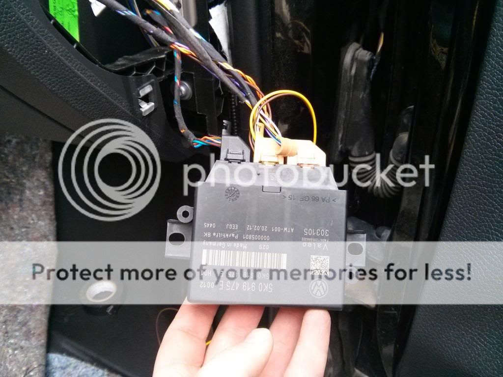
Here is your now, plugged in, module.

And this is how we mounted it. Tape didn’t do anything so I wedged it in.
VCDS CODING BUM, BUM, BUM!
Now time for the fun! VCDS Coding! ATTACH THE BATTERY AGAIN AND TURN THE CAR ON. The module is on switched power....

First click the CAN Gateway > Installation List

Check 10-Park/Steer Assist and save the coding.

You should now see this fancy new module in the list. Click it.

Hit Coding – 07

Select the correct coding Bit 4 definitely and the others if you have them.

Check Bit 0 if you have an Auto, just know we can’t be friends if you do….

Select the correct model… 01 is correct for the MK6 Golf Hatch.
Hit exit and save the coding. If you get a prompt about a shop code just click ok and save the code.
Now make sure everything is plugged in, yes I know the car is in pieces just drag the bumpers close enough to plug them in and make sure the sensors are not pointed at the ground.
Turn the car off then back on and press your new shiny button. If you bought the 4 sensor kit just put it in reverse. Reverse will also activate the 8 sensor kit.

It should do this.

And this!
Have a friend cover each sensor to make sure they are reading at the correct location. If they are not figure out which wire goes to each sensor using color code (only one wire per sensor the other two are common between all four) and switch them in the harness at the PDC. We had to do this with the front bumper as it was reading backwards. Right was left and left was right.

This is the distance it turns red and a solid tone.
Troubleshooting:
If you get a single tone and the light goes off check the fault codes in the parking module and clear them. If the fault returns then check what it says to check. Usually one of the harnesses or buzzers is not connected.
If all is well you can now put the car back together again the reverse of removal. When putting on the front bumper, be sure your sensors fit into the cutouts in the foam.
PLA 2.0 Specifics
So for PLA 2.0 there are a few differences in the install. I bought THIS KIT. It's currently on sale for $418. Remember to request 4 of the angled holders, if you dont you will need to mount them in the wheel arches like the mk7 or it won't work well since the sensors will not be perpendicular to the car.
Differences are:
The length of the harnesses dictated that I install the module in the rear instead of the front so I mounted it with double sided sticky tape behind the carpet on the passenger side of the hatch. All wires were ran up the passenger side to the center console and CAN Gateway, which is an identical install except adding the 2nd button. The park assist button lighting was in series with the park sensor button so you still only make one connection there.

Here is grommet going to the rear bumper.

The finished install of the module. (If you have steel fish tape you can fish the wires through the channel above the wheel well.)
The extra sensors are pretty easy in the front. You will need a tapered bit at least 1 1/8 inches in size as the hole is pretty large. The front sensors have outlines so drill them out like the others. The sensor holder is angled so before gluing, place it in the hole and twist it until you find the position most perpendicular to the car.
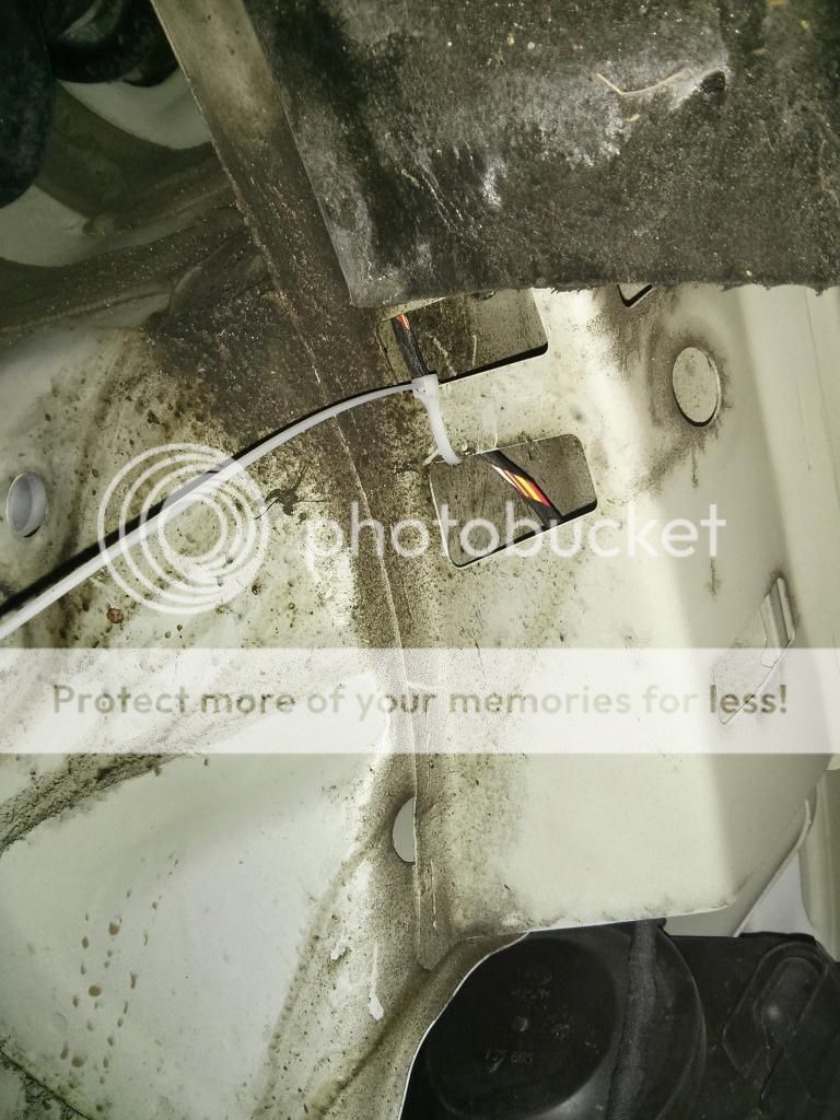
The following pictures are of the wire routing I used to get from the front bumper into the car.

This is the back of the passenger headlight after wheel and all liners were removed.
This is the passageway at the top of the wheel arch.
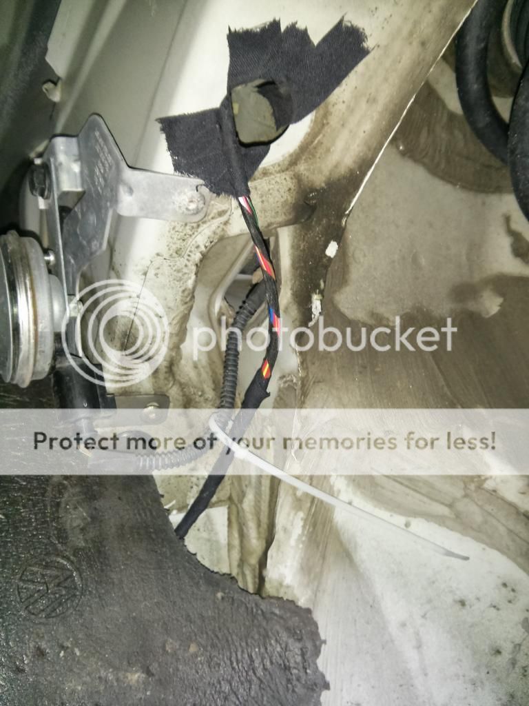
This shows the exit of the passageway and where it goes behind the foam to exit between the fender and body in the door channel.

This shows the wire colors. If you find the sensors are reading wrong (right is left left is right) that center wire is the color you will have to move in the harness (at the module, don't move wires at the sensors!). The red and brown are common between all sensors for power and ground.

This is the side of the bumper after gluing showing the extra sensor. Note how far above the sidemarker it is. There is no interference what so ever.
Now on to the rear bumper. This one doesn't have outlines for the side sensors since the MK6 never came with PLA 2.0. I took a tie strap and lined it up with the other two holes on that side to make a straight line. Then I marked out about 11 inches from sensor next to it. (seemed to be the most perpendicular to the car I could get it) It also may not hurt to move it an inch or two down from the other sensors. Anyway heres pictures of it finished.


This is the passenger side showing both the license plate light and park sensor harnesses.
ABS Sensors:
Use this DIY http://www.golfmk6.com/forums/showthread.php?t=36862 This is far better than anything I could have wrote. Do clean like SoCalMK6GTI says when putting the new sensors in. It will make things go much faster.
First post became too long so here's the coding instructions.
http://www.golfmk6.com/forums/showpost.php?p=1819154&postcount=30
Here goes my first write up. First of all thanks to thebush121 for buying the sensors and letting me take pictures/help with his car and phd-12v for wiring tips. Also thanks to the authors of the tutorials we used to remove bumpers, route wires, etc. Scroll to the end for the PLA 2.0 specifics! When purchasing the PLA 2.0 kit make sure to request 4 of the angled sensors!
Anyway on to the 8 sensor OPS retrofit!
Some background info:
2011 Golf TDI 2 door
RCD-510 (does not have plug for RVC) OPS works great as you will see
Bold Sport OPS 8 sensor kit
PLA 2.0 Background info:
2012 Golf TDI 4 door
RNS-315
For the TL;DR crowd... Finished product.
Parallel Parking
http://youtu.be/PsABB-AE_9Q
Bay Space Parking
http://youtu.be/1A5aTp2LyRQ
Tools required:
- Metric socket set
- Various socket wrench extensions
- T20 torx bit
- Utility knife
- Tapered drill bit (At least 11/16 size)
- Coat hangar or something similar to pull wire through the dash
- Gorilla glue epoxy (sets quickly)
- Jack and stands
- Trim removal tools
- Solder iron and solder
- Heat Shrink
- Fabric/friction tape
- Electrical tape
- Masking tape
- Double sided sticky tape
- Terminal pin removal tool
- Plastic stick on wire holders
- Silicon adhesive
- Steel fish tape
- PLA 2.0 1-1/8in tapered bit
Rear Bumper Removal
We will start with the Rear Bumper removal and sensor install.
First remove the outer lights by pulling back the carpet, unclipping the wires, and unscrewing the white screw. Pull the lights straight away from the car.
Removing the Rear bumper is actually pretty simple. Here are the screw locations:
Then remove all 12 screws (4 in each wheel well and 4 on the bottom edge). You DO NOT need to remove the valance; it all comes off as one piece.
There will be clips on either side on the quarter panel. Unsnap these by pulling straight out from the side of the car
Next pull the bumper cover up and over these three clips.
Use trim tools to push up on these two clips while pulling the bumper cover away from the car
Do these steps on both sides, preferably at the same time with two people and the bumper will come off. Don’t forget to remove the electrical connector for the license plate lights before walking away with the bumper cover! When placing the cover back on it’s the reverse of removal but remember to line up the lip below the hatch with the groove in the bumper cover or your hatch won’t close all the way! (Ask me how I know….)
Now you have a naked car! See that harness laying to the right? That’s the old license plate harness. Bring it inside with the bumper cover you will need it.
Sensor install:
You will see 4 of these outlines inside the bumper cover, use a small drill bit to punch through the center of them from the inside of the bumper. Clean up these spots if your cover is dirty like this one.
Then tape the bumper up with painters tape/masking tape on the outside to protect the paint.
Then drill the holes with the tapered bit to about 11/16 or 18mm. Test fit the sensors and if they are a little tight or don’t fit flush on the outside without force drill it out just a little more. Just take it slow on the first few, can always make a hole larger but can’t make it any smaller!
These are the sensors after gluing. We used a silicon adhesive but once we got to the front bumper one kept falling off hence the recommendation of gorilla glue epoxy. Basically just remove tape, sand the hole to remove any burrs, and sand inside under the sensor holder to give the glue something to stick to. Then mix the epoxy and put a dab on the sensor holder and stick it on the bumper in a way that makes it flush on the outside of the bumper. You might have to hold it there for a bit till glue gets tacky enough to hold the sensor in place. Here are some pictures of the finished bumper with wiring installed. The wiring will basically clip in where the license plate harness was. You will get a few more clips in the kit to attach the wiring to the factory points.
LET THE GLUE DRY FOR AT LEAST A FEW HOURS BEFORE MESSING WITH THE SENSORS!
You will need to splice in the old license plate power as this new harness replaces the license plate harness. Just cut the old harness to the length you need and remove the pins from the end of the new harness pictured above by removing the purple C piece you can see above, unsnapping the body, and use the pin removal tool. Both old and new will have the same color code for the lights brown and grey/brown. (pins 1+2 on the new harness) Fill the holes with silicon on the harness before snapping it all back together to retain water resistance. Take the two pins liberated from the new harness, cut off the pins, strip the wires and solder/heatshrink to old harness. If you ever have to remove the bumper again you should be able to disconnect both sets of wires at the entry point to the body. (Sorry no pictures of this one… plain forgot. I’ll get some when I install the PLA 2.0 on my Golf)
Front Bumper:
The front bumper is a repeat of the drilling/sanding/gluing/wire routing process so I won’t go over that one again. To pull the front bumper use this DIY (we didn’t take pictures as it was day two and we wanted to get it done) http://www.vwgolf.net.au/showthread.php?7265-MK6-Front-Bumper-Removal
Only caveat I have with that DIY is after taking the bumper off I believe the upper grill does not need to be removed first. Just take off the screws on top and remove it with the rest of the cover as it just snaps into it.
Now that you have your sensors glued and attached pull the foam off the front bumper. Now test fit it into the cover. You will have to cut notches into the foam for the front two sensors as shown above and in the next few pictures.
In the above picture you will see the wire on top of the foam. Glue your plastic wire holders to the bumper cover above the foam and snap this wire into them once the glue dries.
So at this point you should have two bumpers with sensors + harnesses installed and a front foam piece with notches cut into it. Oh and a naked car that will become nakeder. Is that even a word? Haha.
Wiring:
Now the difficult part of this this DIY and the source of most of the confusion around it….
A big warning here, do not try to run/test PDC without everything connected (all 8 sensors and both buzzers). IT WILL NOT WORK. IT WILL BEEP AT YOU ONCE THEN GIVE YOU THE FINGER NO MATTER HOW YOU CODE IT. It’s a safety measure to keep people from using a not fully functional system and hitting something. So if you want to test it before putting the car back together connect everything!
First things first, lets get the module wired up to canbus, power, and the button.
The PDC module’s large brown connector is the only one we are dealing with at this moment. This is a good time to disconnect your battery if you haven’t already. Also use the cloth tape to tape up any naked wires on any of the PDC harnesses to prevent rattles before going any further.
This is where we chose to mount the module. Pop the trim off by putting a screwdriver or key in the notch and prying.
Remove the door sill trim by simply pulling up on it by the kick panel and working your way down. Be careful it's easy to break clips. Once this is up the kick panel will pull right off, no screws or clips. Then remove the fuzzy panel under the dash by twisting the two thumb screws.
Remove the radio by using a trim tool to pry the surrounding trim off carefully and removing the four screws surrounding it. Do the same with the climate control below it. If you unplug the airbag light you will have to clear a code in the airbag module with VCDS FYI. Also remove the gearshift trim with your trim tools (move the gearshift to the rear most position to give yourself room) and unscrew the two screws holding the buttons /storage tray. Disconnect any wiring and pull the tray out. Pop out whatever blank you want and pop your snazzy new PDC button in.
In the picture above you can see the orange CANBUS wires already fished through the dash from the passenger side those go all the way to the CAN Gateway above the accelerator. Fish all other wires except the purple buzzer and brown ground to the radio opening including the wiring for the button.
Remove the foot vents on the drivers side. Depending on the year of your car there will be either two screws or one screw and a zip tie. It will probably hit you in the face when unscrewed.
Once the footwell vent is off you will see this guy. Disconnect it (without cutting your thumb like me) and to remove the housing, cut the ziptie, press the red tab seen in this picture, and slide the red housing off. Depending on the model of your car the pins may vary but the two needing to be removed will be the same orange/black and orange/brown of the PDC wires. On this Golf they were pin 6 and 16. Remove these from the housing by pressing the spring in the window and pulling. If you’re confused do a search on Youtube for VW terminal removal.
These wires will plug into the female plug from the PDC (pin1/3) and the male will plug into the gateway in the same spots as the wires you removed. You should end up with the above once you slide the red housing back on to the gateway connector. Which you can now reconnect, CANBUS COMPLETE! Don’t grab a celebratory beer quite yet though.
(On a side note if anyone was wondering where the footwell temperature sensor for climatic is installed by VW its in the background)
Now on to the button and power!
Using your terminal tools again remove the brown and grey wires from the ESP button and plug them into the familiar female connector above into pins 1/3. Make sure to go brown to brown and grey to grey. Then plug the male brown and grey from the PDC button into the ESP button. You should end up with the above.
Now whip out those solder skills and solder the remaining green/black wire to +12v on the power outlet. Cover with electrical tape or heat shrink. The connector on the green/black PDC wire can be cut off. I believe it was meant to go into the fuse panel but it doesn’t fit into any of the holes that we tried. Plus this is so much easier.
You can now connect the buttons/+12v outlet and put it back in place.
Pull the shell off the module connector and plug the button wire or wires into the correct place. I don’t know the correct pins off hand but the label on the module will say. As you can see this one got messed up by double sided tape.
You will see a grounding nut behind the kick panel you removed attach the brown ground wire there.
Now the Rear bumper… This is on the passenger side right next to the bumper mount and is the grommet the license plate light passes through. Cut a small hole and push the rear interior harness through after taking the shell off the connector to make it smaller. Ziptie it to the license plate wire once you have the length you want outside the car.
Another picture of it.
It will come up on the other side of this carpet. Remove the bottom hatch trim by pulling the sides in then the bottom over the luggage hooks and straight up. Be careful the clips break easy. Run the wire under the back seat and down the passenger side to the module location. Coil up any remaining wire behind the carpet above.
Run the purple buzzer wires back to this same spot and mount the buzzer with double sided sticky tape behind the carpet.
Rear bumper wiring is now complete, huzzah!
The front bumper is a bit trickier.
Pull the wheel and the wheel well cover reveal your wires path. There is a channel in the fender for easy wire routing from the washer fluid reservoir to a gap behind the foam piece that leads to the door. Zip tie the wire where appropriate.
These two pictures are the inside and outside pictures of how the front wiring gets to the module. Stick your head under the passenger dash and look above where the kickpanel sits and you will see a plastic plug. Take an extension and give this plug a few taps with a mallet or just your hand and it will pop out. Cut a slit run the wire sans shell through the plastic cap and once you have pulled the length you want into the car silicon the hell out of the cap to keep water out. Then curl extra wire in the dash. Front is now D-U-N, done! Oh wait isn’t there a pesky front buzzer?
Bam, problem solved. It’s covered because it is obscenely loud and the volume adaptation in VCDS does nothing!
Here is your now, plugged in, module.
And this is how we mounted it. Tape didn’t do anything so I wedged it in.
VCDS CODING BUM, BUM, BUM!
Now time for the fun! VCDS Coding! ATTACH THE BATTERY AGAIN AND TURN THE CAR ON. The module is on switched power....
First click the CAN Gateway > Installation List
Check 10-Park/Steer Assist and save the coding.
You should now see this fancy new module in the list. Click it.
Hit Coding – 07
Select the correct coding Bit 4 definitely and the others if you have them.
Check Bit 0 if you have an Auto, just know we can’t be friends if you do….
Select the correct model… 01 is correct for the MK6 Golf Hatch.
Hit exit and save the coding. If you get a prompt about a shop code just click ok and save the code.
Now make sure everything is plugged in, yes I know the car is in pieces just drag the bumpers close enough to plug them in and make sure the sensors are not pointed at the ground.
Turn the car off then back on and press your new shiny button. If you bought the 4 sensor kit just put it in reverse. Reverse will also activate the 8 sensor kit.
It should do this.
And this!
Have a friend cover each sensor to make sure they are reading at the correct location. If they are not figure out which wire goes to each sensor using color code (only one wire per sensor the other two are common between all four) and switch them in the harness at the PDC. We had to do this with the front bumper as it was reading backwards. Right was left and left was right.
This is the distance it turns red and a solid tone.
Troubleshooting:
If you get a single tone and the light goes off check the fault codes in the parking module and clear them. If the fault returns then check what it says to check. Usually one of the harnesses or buzzers is not connected.
If all is well you can now put the car back together again the reverse of removal. When putting on the front bumper, be sure your sensors fit into the cutouts in the foam.
PLA 2.0 Specifics
So for PLA 2.0 there are a few differences in the install. I bought THIS KIT. It's currently on sale for $418. Remember to request 4 of the angled holders, if you dont you will need to mount them in the wheel arches like the mk7 or it won't work well since the sensors will not be perpendicular to the car.
Differences are:
- Location of Module
- 4 more sensors
- 2nd button
- ABS sensors
- Coding of additional modules
The length of the harnesses dictated that I install the module in the rear instead of the front so I mounted it with double sided sticky tape behind the carpet on the passenger side of the hatch. All wires were ran up the passenger side to the center console and CAN Gateway, which is an identical install except adding the 2nd button. The park assist button lighting was in series with the park sensor button so you still only make one connection there.
Here is grommet going to the rear bumper.
The finished install of the module. (If you have steel fish tape you can fish the wires through the channel above the wheel well.)
The extra sensors are pretty easy in the front. You will need a tapered bit at least 1 1/8 inches in size as the hole is pretty large. The front sensors have outlines so drill them out like the others. The sensor holder is angled so before gluing, place it in the hole and twist it until you find the position most perpendicular to the car.
The following pictures are of the wire routing I used to get from the front bumper into the car.
This is the back of the passenger headlight after wheel and all liners were removed.
This is the passageway at the top of the wheel arch.
This shows the exit of the passageway and where it goes behind the foam to exit between the fender and body in the door channel.
This shows the wire colors. If you find the sensors are reading wrong (right is left left is right) that center wire is the color you will have to move in the harness (at the module, don't move wires at the sensors!). The red and brown are common between all sensors for power and ground.
This is the side of the bumper after gluing showing the extra sensor. Note how far above the sidemarker it is. There is no interference what so ever.
Now on to the rear bumper. This one doesn't have outlines for the side sensors since the MK6 never came with PLA 2.0. I took a tie strap and lined it up with the other two holes on that side to make a straight line. Then I marked out about 11 inches from sensor next to it. (seemed to be the most perpendicular to the car I could get it) It also may not hurt to move it an inch or two down from the other sensors. Anyway heres pictures of it finished.
This is the passenger side showing both the license plate light and park sensor harnesses.
ABS Sensors:
Use this DIY http://www.golfmk6.com/forums/showthread.php?t=36862 This is far better than anything I could have wrote. Do clean like SoCalMK6GTI says when putting the new sensors in. It will make things go much faster.
First post became too long so here's the coding instructions.
http://www.golfmk6.com/forums/showpost.php?p=1819154&postcount=30
Last edited:

