snowboardgti
Ready to race!
*Warning, I’m not responsible for anything below. Everything is for informational purposes only.
Introduction:
So I have a 2010 GTI and when I got the car, I knew little or nothing about getting projector with AFS. So now, I’ve taken matters into my own hands to make sure I get my own AFS. I didnt want to spend money on getting OEM projectors w/ AFS and ignoring the AFS feature by simply putting an adapter and calling it a day. I did find Kufatec’s kit, but I found it way to hard to justify an additional 520 for AFS. The funny thing was I actually did buy an AFS kit from them almost a year ago for 320! I returned it because it was missing my adapter and I had a change of plans anyways. I don’t know what caused the price increase... figures... Anyways, I’ll try my best to explain everything possible below and answer PMs or questions to help you guys out. I have received a lot of help from vwvortex and golfmk6 and now its time to give back")
First off, the difficulty in this project I’d say is comparable to installing a sound system. You have to remove your rear driver side panel, floor channel panel (don’t know the exact name) glove box panel, and fuse (headlight switch) area. Then you have to know how to get through the firewall behind the accelerator pedal (if you’ve installed an amp, this should be a piece of cake), get behind the rear well grommet (pretty easy here too), install some pins into the CECM, control module and fuse and then an annoying part, get the wiring behind and underneath the rain guard to get your wires from your passenger side over to the driver side and then into the firewall.
Here’s how the leveling system works:
You have a pully/lever system on your rear suspension which tells your control module to either tell your lights to aim up or down. Then you have your can bus system you splice into which will tell your lights to move left or right. So both systems communication to your AFS Control Module which I’ll explain below on how to make.
Your pinouts to your AFS control module:
Understand this diagram and then the parts below will make more sense

Parts:
This was the most time consuming part for me, going back and forth to see exactly which wires and pins I needed so hopefully I spared you guys some time. If youre willing to fork out the time, you can save yourself almost 200 bucks versus buying a kit. First off, the part where youll save the most money is buying the AFS control module and level sensor used or from a junk yard.
Rear Level Sensor
1 Rear Level Sensor 1K0941273L
5 Sensor Mounting Bolts N10430104
5 Riveted Cap Nuts N10597701
1 Grommet 6N0906102
1 Corrugated Pipe N90635517
2 Cable Ties N90666101
1 HOUSING 4 Pin Sensor 4B0973712
3 Terminal Pins N10335807 / 964274-3
14-Pin Headlight Harness
2 HOUSING 14 Pin Harness 1J0973737
11 Small Terminal Pins N10335807 / 964274-3
5 Large Terminal Pins N90684405 / 927773-3
2 10A Fuse N10261503
*note one small and one large terminal pin is going to be used for the CECM high beam trigger.
AFS Module
1 AFS Control Module 5M0907357C
1 HOUSING 26 Pin AFS Control Module 7M3972726B
9 Terminal Pins N90764701 (this doesnt seem to be the right pt. number) / 963715-1
**Other things you’ll need:
Grommets for headlight and level sensor harness/terminals
Wire stripper
Molex crimp tool
Wire terminal removers
Friction tape
Also, for the part numbers on the pins, the numbers after the ‘/’ are TYCO part numbers if you prefer to get it from them. And the quantity for pins are quantity needed INDIVIDUALLY. However, I recommend you get more than plenty in case you make a mistake or something.
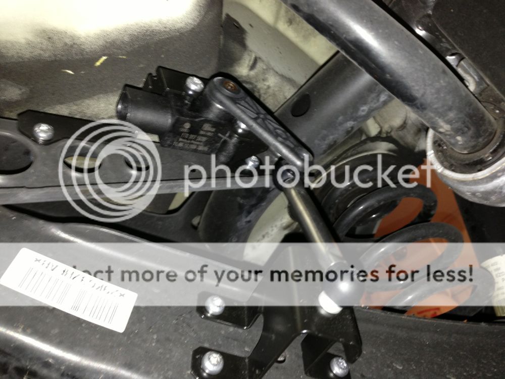
Installing the Rear Level Sensor:
There are 5 holes in the driver rear suspension. With the nuts and rivets shown in the parts diagram, you install it, make sure the lever is pointing outwards! The harness is a 4 pin harness (check wiring diagram)
Then use the ‘corrugated pipe’ to cover the wires and guide the wires using the OEM zip tie holders to the rear well (have to remove cover to find grommet). Guide the wire down inside the wire channel along the side of the car and lead it towards the firewall then across the glove box into the AFS module.
Parts:

Remove two screws to get access into the cabin


There are two holes for the oem zip ties


When making the 4 pin terminal for the rear level sensor harness, make sure to remove the pink terminal lock slider with a flat head. (you’ll have to do this for the 10 pin headlight harness too)

We will wire the 3 pins into the 26 pin housing in the end.
Your pinouts from your 10 pin harness to your 14 pin harness:
I prefer to do this method of de-pinning from your old harness to the new one rather than using an adapter. This will help save clutter from having excess wiring and adapters and give you a clutterfree and more OEM look.
While almost everything stays the same, here are the differences:
-There will be additional pin for ground (for the ballast)
-Pins 1,2 and 4 on the NEW 14 pin harness are for AFS. This is what will allow you to move your headlights in all direction. 1 and 2 are from your AFS control module while pin 4 (powering your AFS module thats underneath the headlight) will be plugged into fuse 5(left), 6 (right). these are actual OEM locations for powering AFS.
-Pin 4 from your OLD 10 pin harness will be moved to pin 12 for DRL, yum. You will HAVE to change your big terminal to the smaller terminal (N10335807).
-Pin 8 from your OLD 10 pin harness will be going to NOTHING.
-Pin 11 on the NEW 14 pin harness is your high beam shutter. This wire will go into your CECM gold connector, 48 and 49. I used parts N90684405 and N10335807 which are not OE but works completely fine and stays secured.
You just have to make sure you UNLOCK the pin harness to ensure removal. To unlock the 10 pin harness, there is a purple slider within the harness. Pull that out using a flat head. Then for the 14 pin harness, you have to move the whole purple block and ‘click’ it out.
Installing the Wires from the headlights.
There should be 4 wires on each side of the headlights (two can wires, afs power and high beam trigger wire). The wires on the drive side will simply go into the firewall. It helps removing the whole battery box assembly to get easier access. For the passanger side, the wires will lead back around the coolant and back into the rain tray. Then it’ll come back out towards the driver side and go back into the firewall the same way.
Removing pins:


Now OEM harness, no adapter shenanigans:

Pulling the wire through the firewall:


Under the glove box, behind the fan motor, there is a orange/black(HIGH) and orange/brown(LOW) wire you need to splice into for the AFS CAN BUS pins.

Get access behind the fuse box for 5, 6 for AFS Control Module Power. Perfect opportunity to install your parking light trigger wire for your euro switch

Installing your AFS Module:
Underneath your glove box, there are two screws that are supposed to hold your AFS Module. The downside to the kufatec harness is that its not long enough to reach all the way to the glove box because youre supposed find a random spot underneath the steering wheel column.
As for making the harness, you need a molex crimp tool. You can find these either at an electronic store or on ebay/amazon. Then youll wire up the pins as shown in the wiring diagram.
Glove box disassembled:

Installing it in the OEM location

Making the AFS Harness:


VAG COM:
My model is a 2010 Halogen w/ fogs (GTI). I DID NOT HAVE TO CHANGE/UPGRADE MY CECM. While I would like to help you with CECM for you golf owners, I have NO KNOWLEDGE whatsoever so I can’t help you on this.
With LEDs and LED Headlights installed, I had to code byte 18 to 21. I had the hardest time trying to figure out why my LEDs on one side wouldnt turn on.. All my wiring was perfectly fine, just had to change it to 21
Some Help here:
http://golfmk6.com/forums/showpost.php?p=597793&postcount=87
http://www.mk6golfgti.co.uk/forum/index.php?topic=113.0
Most importantly, you have to go into 19 CAN Gateway, and check 55 - Xenon Range. This lets your car know you've installed your AFS Control Module! Then run some tests to make sure everything works!


Then you can go into 55 Xenon range and run some tests


Some things to mention
-While some VW models need front sensors, the MK6 Golf/GTI models ONLY NEED the rear sensor (OEM is configured this way)
-If one side of the LEDs arn't working, its probably your byte 18 coding
-Expect this project to take anywhere from 3-4 days as a first timer (if you’ve done audio installation, you could probably do it in 1-2 days)
-After messing with some reps, I can finally see why there are some hardcore OEMers out there. On my aftermarket LED lights, the 10 pin harness broke while I was connecting it. Also, the quality of just ‘everything’ is not the same. It sounds cheesy but the plastic material just felt cheap. Also, there were way too many blemishes on the paint. Especially the chrome! In sunlight, you could clearly see the swirl marks on the ‘eyelids’ which was why I repainted my reps ‘aluminum gray’ when I retrofitted it. On the OEM, the LEDs are nice and bright, the way OEMs should be (audis, mercedes, porsche...). The LEDs on my reps were seriously a joke. I didnt even keep em on as DRLs cause it was way too embarrassingly dim. Plus OEM leds are actually white, not some corny ass 5/6k color.
Introduction:
So I have a 2010 GTI and when I got the car, I knew little or nothing about getting projector with AFS. So now, I’ve taken matters into my own hands to make sure I get my own AFS. I didnt want to spend money on getting OEM projectors w/ AFS and ignoring the AFS feature by simply putting an adapter and calling it a day. I did find Kufatec’s kit, but I found it way to hard to justify an additional 520 for AFS. The funny thing was I actually did buy an AFS kit from them almost a year ago for 320! I returned it because it was missing my adapter and I had a change of plans anyways. I don’t know what caused the price increase... figures... Anyways, I’ll try my best to explain everything possible below and answer PMs or questions to help you guys out. I have received a lot of help from vwvortex and golfmk6 and now its time to give back
First off, the difficulty in this project I’d say is comparable to installing a sound system. You have to remove your rear driver side panel, floor channel panel (don’t know the exact name) glove box panel, and fuse (headlight switch) area. Then you have to know how to get through the firewall behind the accelerator pedal (if you’ve installed an amp, this should be a piece of cake), get behind the rear well grommet (pretty easy here too), install some pins into the CECM, control module and fuse and then an annoying part, get the wiring behind and underneath the rain guard to get your wires from your passenger side over to the driver side and then into the firewall.
Here’s how the leveling system works:
You have a pully/lever system on your rear suspension which tells your control module to either tell your lights to aim up or down. Then you have your can bus system you splice into which will tell your lights to move left or right. So both systems communication to your AFS Control Module which I’ll explain below on how to make.
Your pinouts to your AFS control module:
Understand this diagram and then the parts below will make more sense
Parts:
This was the most time consuming part for me, going back and forth to see exactly which wires and pins I needed so hopefully I spared you guys some time. If youre willing to fork out the time, you can save yourself almost 200 bucks versus buying a kit. First off, the part where youll save the most money is buying the AFS control module and level sensor used or from a junk yard.
Rear Level Sensor
1 Rear Level Sensor 1K0941273L
5 Sensor Mounting Bolts N10430104
5 Riveted Cap Nuts N10597701
1 Grommet 6N0906102
1 Corrugated Pipe N90635517
2 Cable Ties N90666101
1 HOUSING 4 Pin Sensor 4B0973712
3 Terminal Pins N10335807 / 964274-3
14-Pin Headlight Harness
2 HOUSING 14 Pin Harness 1J0973737
11 Small Terminal Pins N10335807 / 964274-3
5 Large Terminal Pins N90684405 / 927773-3
2 10A Fuse N10261503
*note one small and one large terminal pin is going to be used for the CECM high beam trigger.
AFS Module
1 AFS Control Module 5M0907357C
1 HOUSING 26 Pin AFS Control Module 7M3972726B
9 Terminal Pins N90764701 (this doesnt seem to be the right pt. number) / 963715-1
**Other things you’ll need:
Grommets for headlight and level sensor harness/terminals
Wire stripper
Molex crimp tool
Wire terminal removers
Friction tape
Also, for the part numbers on the pins, the numbers after the ‘/’ are TYCO part numbers if you prefer to get it from them. And the quantity for pins are quantity needed INDIVIDUALLY. However, I recommend you get more than plenty in case you make a mistake or something.
Installing the Rear Level Sensor:
There are 5 holes in the driver rear suspension. With the nuts and rivets shown in the parts diagram, you install it, make sure the lever is pointing outwards! The harness is a 4 pin harness (check wiring diagram)
Then use the ‘corrugated pipe’ to cover the wires and guide the wires using the OEM zip tie holders to the rear well (have to remove cover to find grommet). Guide the wire down inside the wire channel along the side of the car and lead it towards the firewall then across the glove box into the AFS module.
Parts:
Remove two screws to get access into the cabin
There are two holes for the oem zip ties
When making the 4 pin terminal for the rear level sensor harness, make sure to remove the pink terminal lock slider with a flat head. (you’ll have to do this for the 10 pin headlight harness too)
We will wire the 3 pins into the 26 pin housing in the end.
Your pinouts from your 10 pin harness to your 14 pin harness:
I prefer to do this method of de-pinning from your old harness to the new one rather than using an adapter. This will help save clutter from having excess wiring and adapters and give you a clutterfree and more OEM look.
While almost everything stays the same, here are the differences:
-There will be additional pin for ground (for the ballast)
-Pins 1,2 and 4 on the NEW 14 pin harness are for AFS. This is what will allow you to move your headlights in all direction. 1 and 2 are from your AFS control module while pin 4 (powering your AFS module thats underneath the headlight) will be plugged into fuse 5(left), 6 (right). these are actual OEM locations for powering AFS.
-Pin 4 from your OLD 10 pin harness will be moved to pin 12 for DRL, yum. You will HAVE to change your big terminal to the smaller terminal (N10335807).
-Pin 8 from your OLD 10 pin harness will be going to NOTHING.
-Pin 11 on the NEW 14 pin harness is your high beam shutter. This wire will go into your CECM gold connector, 48 and 49. I used parts N90684405 and N10335807 which are not OE but works completely fine and stays secured.
You just have to make sure you UNLOCK the pin harness to ensure removal. To unlock the 10 pin harness, there is a purple slider within the harness. Pull that out using a flat head. Then for the 14 pin harness, you have to move the whole purple block and ‘click’ it out.
Installing the Wires from the headlights.
There should be 4 wires on each side of the headlights (two can wires, afs power and high beam trigger wire). The wires on the drive side will simply go into the firewall. It helps removing the whole battery box assembly to get easier access. For the passanger side, the wires will lead back around the coolant and back into the rain tray. Then it’ll come back out towards the driver side and go back into the firewall the same way.
Removing pins:
Now OEM harness, no adapter shenanigans:
Pulling the wire through the firewall:
Under the glove box, behind the fan motor, there is a orange/black(HIGH) and orange/brown(LOW) wire you need to splice into for the AFS CAN BUS pins.
Get access behind the fuse box for 5, 6 for AFS Control Module Power. Perfect opportunity to install your parking light trigger wire for your euro switch
Installing your AFS Module:
Underneath your glove box, there are two screws that are supposed to hold your AFS Module. The downside to the kufatec harness is that its not long enough to reach all the way to the glove box because youre supposed find a random spot underneath the steering wheel column.
As for making the harness, you need a molex crimp tool. You can find these either at an electronic store or on ebay/amazon. Then youll wire up the pins as shown in the wiring diagram.
Glove box disassembled:
Installing it in the OEM location
Making the AFS Harness:
VAG COM:
My model is a 2010 Halogen w/ fogs (GTI). I DID NOT HAVE TO CHANGE/UPGRADE MY CECM. While I would like to help you with CECM for you golf owners, I have NO KNOWLEDGE whatsoever so I can’t help you on this.
With LEDs and LED Headlights installed, I had to code byte 18 to 21. I had the hardest time trying to figure out why my LEDs on one side wouldnt turn on.. All my wiring was perfectly fine, just had to change it to 21
Some Help here:
http://golfmk6.com/forums/showpost.php?p=597793&postcount=87
http://www.mk6golfgti.co.uk/forum/index.php?topic=113.0
Most importantly, you have to go into 19 CAN Gateway, and check 55 - Xenon Range. This lets your car know you've installed your AFS Control Module! Then run some tests to make sure everything works!
Then you can go into 55 Xenon range and run some tests
Some things to mention
-While some VW models need front sensors, the MK6 Golf/GTI models ONLY NEED the rear sensor (OEM is configured this way)
-If one side of the LEDs arn't working, its probably your byte 18 coding
-Expect this project to take anywhere from 3-4 days as a first timer (if you’ve done audio installation, you could probably do it in 1-2 days)
-After messing with some reps, I can finally see why there are some hardcore OEMers out there. On my aftermarket LED lights, the 10 pin harness broke while I was connecting it. Also, the quality of just ‘everything’ is not the same. It sounds cheesy but the plastic material just felt cheap. Also, there were way too many blemishes on the paint. Especially the chrome! In sunlight, you could clearly see the swirl marks on the ‘eyelids’ which was why I repainted my reps ‘aluminum gray’ when I retrofitted it. On the OEM, the LEDs are nice and bright, the way OEMs should be (audis, mercedes, porsche...). The LEDs on my reps were seriously a joke. I didnt even keep em on as DRLs cause it was way too embarrassingly dim. Plus OEM leds are actually white, not some corny ass 5/6k color.
Last edited: