Could be MAF sensor, vacuum leak, cracked intercooler, or leaking/cracked turbo intercooler hose
Pulled the diagnostic procedures (formatted for legibility):
MAF Sensor, Checking
Use only gold-plated terminals when servicing terminals in harness connector of Mass Air Flow (MAF) Sensor -G70- .
-Multimeter.
-Wiring diagram.
-The Mass Air Flow (MAF) Sensor -G70- fuse 1 in Fuse Panel C is OK.
-Battery voltage at least 12.5 volts.
-All electrical consumers such as, lights and rear window defroster, switched off.
-Vehicles with automatic transmission, shift selector lever into position P or N
-A/C switched off.
-Ground connections between engine/transmission/chassis OK.
-Coolant Temperature at least 80 °C.
-Ignition switched off.
-Perform a preliminary check to verify the customers complaint.
-Connect the scan tool.
-Start engine and let it run at idle.
-Using the scan tool, Check the air flow quantity of the Mass Air Flow
(MAF) Sensor -G70- at idle:
Diagnostic text /
Specified value
Air flow quantity at Mass Air Flow (MAF) sensor Engine warmed up, running at idle / 2.00 to 5.00 g/sec
-If specified value is obtained, but DTC memory has a DTC concerning Mass Air Flow (MAF) Sensor -G70- :
Fault may be intermittent. Check the electrical harness connector for damage, corrosion, loose or broken terminals.
-If the specified value was Not obtained:
– Disconnect the Mass Air Flow (MAF) Sensor -G70- electrical harness connector -1-.
– Start the engine and let it run at idle.
– Using a multimeter, check the Mass Air Flow (MAF) Sensor -G70- electrical harness connector terminal 3 to engine Ground.
Specified value: battery voltage.
– Switch the ignition OFF.
If the specified value was Not obtained:
– Remove the fuse 1 in Fuse Panel C. Check the Mass Air Flow (MAF) Sensor -G70- electrical harness connector terminal 3 to Fuse 1 in Fuse Panel C for an open circuit.
Specified value: 1.5 Ω max.
If the specified value was obtained:
If the manufacturers test box is being used, perform the following step.
– Install the test box.
If the manufacturers test box is not being used, perform the following step.
– Remove the Motronic Engine Control Module (ECM) -J623- . Refer to the Repair Manual.
– Using a multimeter, check the Mass Air Flow (MAF) Sensor -G70- electrical harness connector terminals to the Motronic Engine Control Module (ECM) -J623- electrical harness connector T94 terminals for an open circuit.
Mass Air Flow (MAF) Sensor -G70- electrical harness connector terminals (ECM) -J623- electrical connector T94 terminals or test box socket /
Motronic Engine Control Module
1 / 23
2 / 65
4 / 14
5 / 60
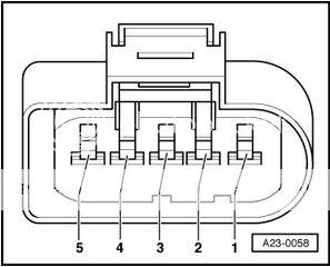
Specified value: 1.5 Ω max.
If the specified value was Not obtained:
– Check the wiring for an open, high resistance or short to ground.
– Check the electrical harness connector for damage, corrosion, loose or broken terminals.
– If necessary, repair the faulty wiring connection.
If no malfunction is detected in the wiring and the voltage supply was OK:
– Replace Mass Air Flow (MAF) Sensor -G70- . Refer to the Repair Manual.
If no malfunction is detected in the wiring and the voltage supply was Not OK:
– Replace the Motronic Engine Control Module (ECM) -J623- . Refer to the Repair Manual.
After the repair work, the following work steps must be performed in the following sequence:
1 - Check the DTC memory. Refer to
Diagnostic Mode 03 - Read DTC Memory.
2 - If necessary, erase the DTC memory. Refer to
Diagnostic Mode 04 - Erase DTC Memory.
3 - If the DTC memory was erased, generate readiness code. Refer to
Readiness Code.
Edited for more clarity + the image of the sensor terminals
