If you have a 4-door and kessy, you will know that only the front door handles have the touch sensors to lock and unlock the doors. The rear door handles do not have these sensors. This DIY shows you how to replace the rear door handles and do the wiring so that the rear door handles also have the touch sensors to lock and unlock the doors.
Parts:
Tools
Instructions
Part 1 - Build wire harness to run between A-pillar and B-pillar
Part 2 - Run harness from A-pillar door connector to B-pillar door connector
Part 3 - Build wire harness to run between rear door handle and B-pillar
Coming soon
Part 4 - Run wire harness from rear door handle to B-pillar
Coming soon
Parts:
- Left door handle with Kessy (driver) 1K8 837 205 or 1K8 837 205H

- Right door handle with Kessy (passenger) 1K8 837 206 or 1K8 837 206H

- 2 x door handle connector 3C0 973 704

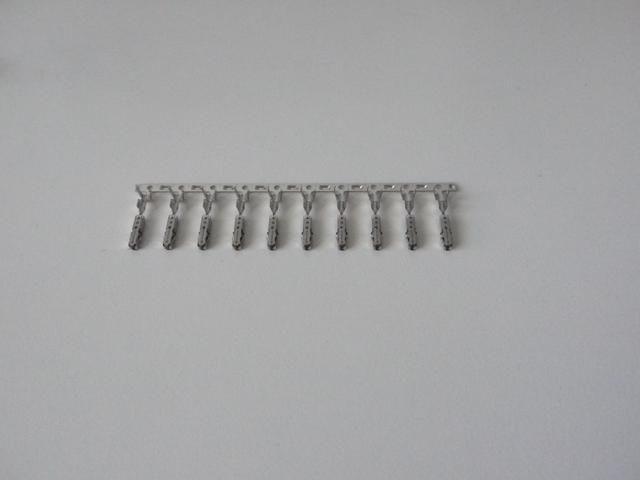
- 4 x repair wires 000 979 030 or 000 979 030E (these are the terminal pins that go into the door handle connector). For some reason 000 979 030E cost about $20 USD per repair wire. I bought 000 979 030 from ebay for $6 USD each + $2.50 USD shipping and it fits into the connector perfectly so don’t waste your money on the ‘E’ version.
- 4 x repair wire 000979020 or buy the terminal pins

- 4 x repair wire 000979150 or buy the terminal pins
- Lots of 0.5mm2 wire
- 8 x Crimp butt connectors

- Electrical tape
- Cloth tape
- Small zip ties
Tools
- Plastic trim removal tools
- Torx screw set
- Terminal pin crimper

- Wire stripper
Instructions
Part 1 - Build wire harness to run between A-pillar and B-pillar
- Cut 4 wires of equal length (I don't remember how much I used but 8 feet is more than enough. I think the actual length you need is 5 feet but I wanted plenty of slack in case I messed up)
- Depending on whether you bought repair wires 000979020 or if you just bought the terminal pins, you want to connect four pins to one end of each wire. In my case, I bought the terminal pins so I crimped them on.


- Use cloth tape and bind the four wires to make your harness. Start the tape about 2-3 inches from the terminal pins and tape about 5 feet of wire. Don't forget to mark the wires with colored tape so you know which end is what.

Part 2 - Run harness from A-pillar door connector to B-pillar door connector
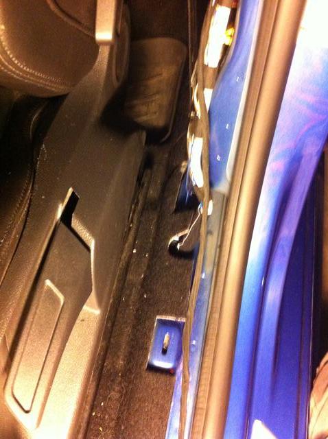
- Remove the door sill trim. It pops off easily. Use this link to guide you if you have never done it before: Click Here
- Remove the lower trim of the B-pillar to expose the car-side door connector. See here for more details: Click Here
- Remove the A-pillar lower trim. The instructions to remove this differ between the passenger side and driver side because of the handle to release the hood. Here are instructions for each side: [Driver side] [Passenger side]
- Release the B-pillar connector from the door side. You need to unhook the rubber accordion thing that protects the wires and then release the connector.

- Release the door connector from the B-pillar (car-side). You can do this because you removed the B-pillar lower trim.

- We need to insert the four pins from our harness in Part 1 into this connector. If you've worked with any type of connectors from other DIYs, you will know that there is always some mechanism that locks the terminal pins to the connector. Usually, the lock mechanism is pink. For this connector, there are two pink pieces that need to be moved. First one is in this picture below. It needs to swivel 90 degrees up. Inspect it and you will see how it needs to swivel.
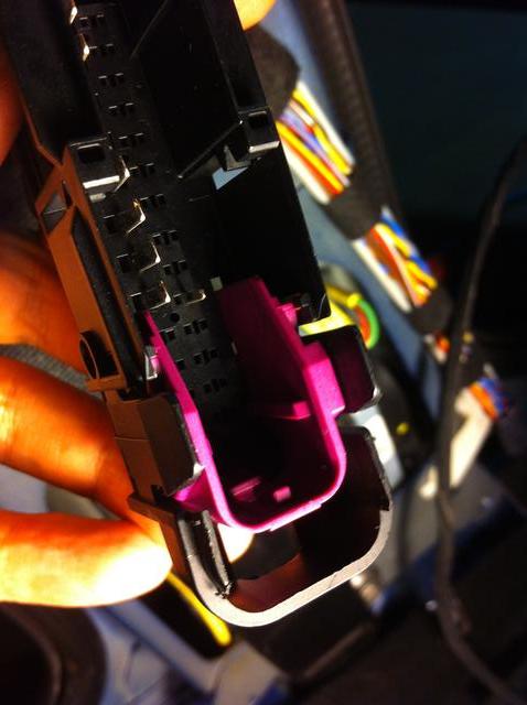

However, before you can swivel this piece, it needs to be unlocked from the side. This image shows it unlocked.

If this isn't clear, just inspect it some more. It's not vert complicated. - Next, take a small flat head screw driver and unlock the second pink lock mechanism by sliding it to the side. You will feel it click when you slide it. It won't slide all the way out. It is possible to slide the lock too far. You will know it is too far if you hear two clicks. You only want it to click once.
- Insert the four pins from Part 1 into slots 14, 15, 16, 17 of the connector. Each pin should click into place. Give it a small tug to make sure it's in place. Then lock up the connector and insert the connector back into the B-pillar. Take note of which color wire you inserted into which slot number.
- Now with the pins inserted into the B-pillar connector, run the wire harness down to the floor (follow existing wires), under the carpet and towards the front of the car to the lower A-pillar.
- Remove the A-pillar door connector. Use the same method as you did with the B-pillar.

- Each wire from the harness in Part 1 now needs to tap into four wires in the A-pillar connector. The wire you inserted into slot 14 of the B-pillar connector needs to tap into wire 14 of the A-pillar connector. 15 to 15. 16 to 16. 17 to 17. Use whatever method you want to tap into the wires. I simply stripped the wires and used electrical tape to wrap it up.

Part 3 - Build wire harness to run between rear door handle and B-pillar
Coming soon
Part 4 - Run wire harness from rear door handle to B-pillar
Coming soon
Last edited: