jacekk1986
New member
- Location
- Poland
- Car(s)
- GTI MK7
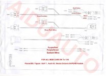
Also, since this thread is long and you may have missed it. If you're ordering a retrofit harness from AliExpress (or wherever, any place that's not OEM) the rear is probably wired as if you're running the harness down the left side of the car. Meaning the first sensor connector on the harness will be for the rear left sensor. It's no problem if you actually run it down the left side of the car.Hello, does anyone have access to xagico pdf for park assist retrofit? All the links i've found are dead. Just ordered the aliexpress kit but getting my head around the wiring is driving me insane!
Here's the whole big .pdf.
Thanks for this info, does this make a difference if my car is LHD or RHD? I'm based in the UK so have RHD. I would imagine wiring down the left side of the car would make more sense? since the connections for can/TIUL is (i'm pretty sure) on the left side of the carAlso, since this thread is long and you may have missed it. If you're ordering a retrofit harness from AliExpress (or wherever, any place that's not OEM) the rear is probably wired as if you're running the harness down the left side of the car. Meaning the first sensor connector on the harness will be for the rear left sensor. It's no problem if you actually run it down the left side of the car.
But if you run it down the right side of the car (factory routing) the rear sensors will be wired in reverse.
Without getting into why the factory routing makes the most sense, just something to keep in mind.
I don't believe it makes a difference. None of the factory parking system wiring goes to/through TIUL anyway.Thanks for this info, does this make a difference if my car is LHD or RHD? I'm based in the UK so have RHD. I would imagine wiring down the left side of the car would make more sense? since the connections for can/TIUL is (i'm pretty sure) on the left side of the car
oh awesome! sooo i can run it along the left side as intended without issue i guess. i must’ve got confused with a different retrofit been doing too much lately hahaI don't believe it makes a difference. None of the factory parking system wiring goes to/through TIUL anyway.
appreciate the help, i have access to elsawin so will check on there which side its situated on for my car.On my LHD drive car the PDC module is under the steering wheel. The PLA 3 module is taller than the PLA 2 module so early mounts needed some modification. Later mounts would work with both PLA 2 and PLA 3 so your 7.5 likely has a later mount.
If your module is on the right side it would be easier, in my opinion, to run the harness on the right side (which is where VW intends).
Ultimately you need to check the wiring harness against the wiring diagram to make sure everything is correct for whichever side you choose.

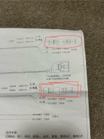
I see, thanks for taking the time to checkI don't know what EX22 is supposed to be. EX30 in my picture below is the center console switch module. Whatever you have there already will remain, but you will add whatever is necessary to match the diagram. E581 is the parallel park button (within) EX30. Pin 4 is for that LED and Pin 7 is for the button actuation. Doesn't matter that you have a SET! button there. The SET! button is part of EX30 but not shown on the parking system diagram. I'll have to check the circled items later this evening.
Are you going from 8 sensors to 12 sensors?
Ah, So you're doing what I did a couple of years ago on my MK7 R. I went through the erwin diagrams to figure out the wiring, which the Chinese directions actually matched up to. The connectors they've provided are to allow you to connect the wiring from the kit to the OE wiring without having to physically splice. They are dovetails and they can make it easier, assuming you have the correct pins for the connector, which based upon my experience worked.I see, thanks for taking the time to check
I guess i'll wire it to pin 4 and 7 and hope for the best, after all it's in the instructions for my supplied kit so it must be the right one
And yes, I've already got front and rear sensors from factory so i'll be going from 8 to 12